Amp Mods · Blues Jr. Standy Switch Mod Kit
Fender Blues Jr Standby Switch
Thanks for purchasing the Blues Jr. Standby Switch Modification Kit.
Optional Tools/Supplies:
- 9/16” nut driver or socket wrench.
- 1/2” nut driver or socket wrench.
- Fine point Sharpie or similar permanent marker.
- Masking Tape
Skills required:
- Basic knowledge of electronics.
- The Ability to follow instructions.
Parts
- Carling Progressive Switch
- Lead with crimped ends
- Power resistor for draining the caps if necessary.
Tools
- Multi-Meter Capable of reading 500V DC
- Phillips Screwdriver
- Pliers with insulated handle
- Safety Goggles
- Alligator Leads
1
Step 1
- WARNING: Performing these modifications WILL void the warranty on your amplifier. Working on amps can be deadly if you do not take proper precautions. Follow these instructions very carefully. If you are at all unsure of your ability to perform these modifications STOP and take your amp to a professional to be modified. You can also send your amp to me for modification.
- No Warranty: This kit and the instructions included do not include any warranty of any kind. The modifications to your amplifier are at your own risk and you agree to completely hold harmless the seller of this kit against any and all claims. Tube amplifiers contain parts that operate at very high temperatures and deadly voltages. If you are not sure of your abilities to perform these modifications then do not perform them.
- Caution: This mod is designed for amps with 120 voltage power transformers. The standby switch will work with 100V, 230V, and 240V power transformers but the connections will be different. Please refer to the schematic for your amp if you have a power transformer other than 120V.
- There is currently no support available for export power transformers.
2
Prep the Amp
- Instructions: Follow these instructions to the letter.
- It’s a good idea to have all the parts and tools you will need laid out before starting in a well lit area.
- Unplug the Amp and put on your safety goggles.
3
Step 3
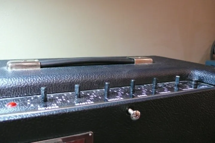
- Remove the 6 screws holding on the back panel and remove the panel. If the back panel does not come off easily you can loosen the two chassis screws on the side of the amp about a half turn each.
4
Step 4
- Drain the Filter Caps: The filter caps on your amp may be drained already but you must follow these steps to insure that any deadly voltage is removed from the amp before you begin work. Test the voltage across the filter caps. Set your multi meter to DC and measure the voltage across the positive and negative side of any of the filter caps. If the voltage reads higher than 10 volts, then you need to drain the caps.
5
Step 5
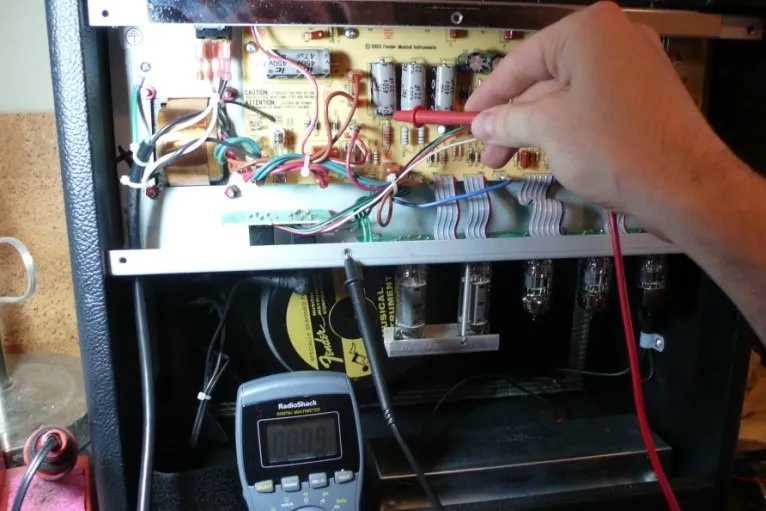
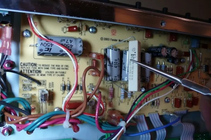
- Using the insulated pliers to hold the power resistor touch one lead of the resistor to the negative side of the filter cap and the other to the positive side, leave the leads in contact with the power resistor for 30 seconds and measure again. Keep repeating this step until the voltage reads below 10V.
- Capacitors can recharge even when the amp is not plugged in!!!
- After the filter caps are drained take an alligator lead and clip one end to the positive lead of the filter cap and the other end to the chassis and leave it there until you are done with your work. This will prevent the filter caps from re-charging.
6
Step 6
- Clip all of the wire ties.
7
Step 7
- Remove the current power switch and save it as it may come in handy someday.
8
Blues Jr. USA
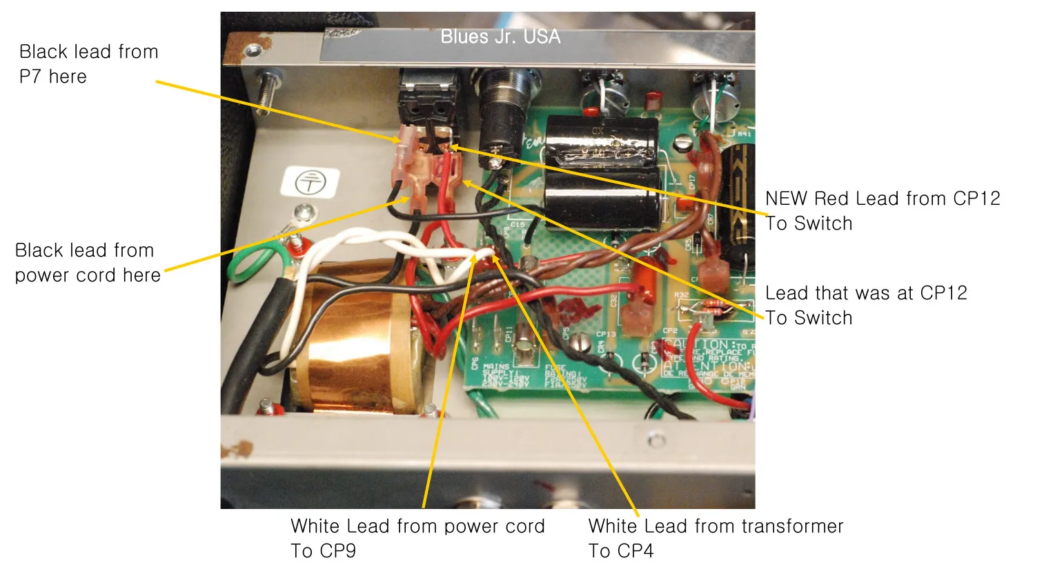
- Install new Standby switch as follows:
- Black lead from P7 here
- Black lead from power cord here
- NEW Red Lead from CP12 To Switch
- Lead that was at CP12 To Switch
- White Lead from power cord To CP9
- White Lead from transformer To CP4
9
Blues Jr. MIM
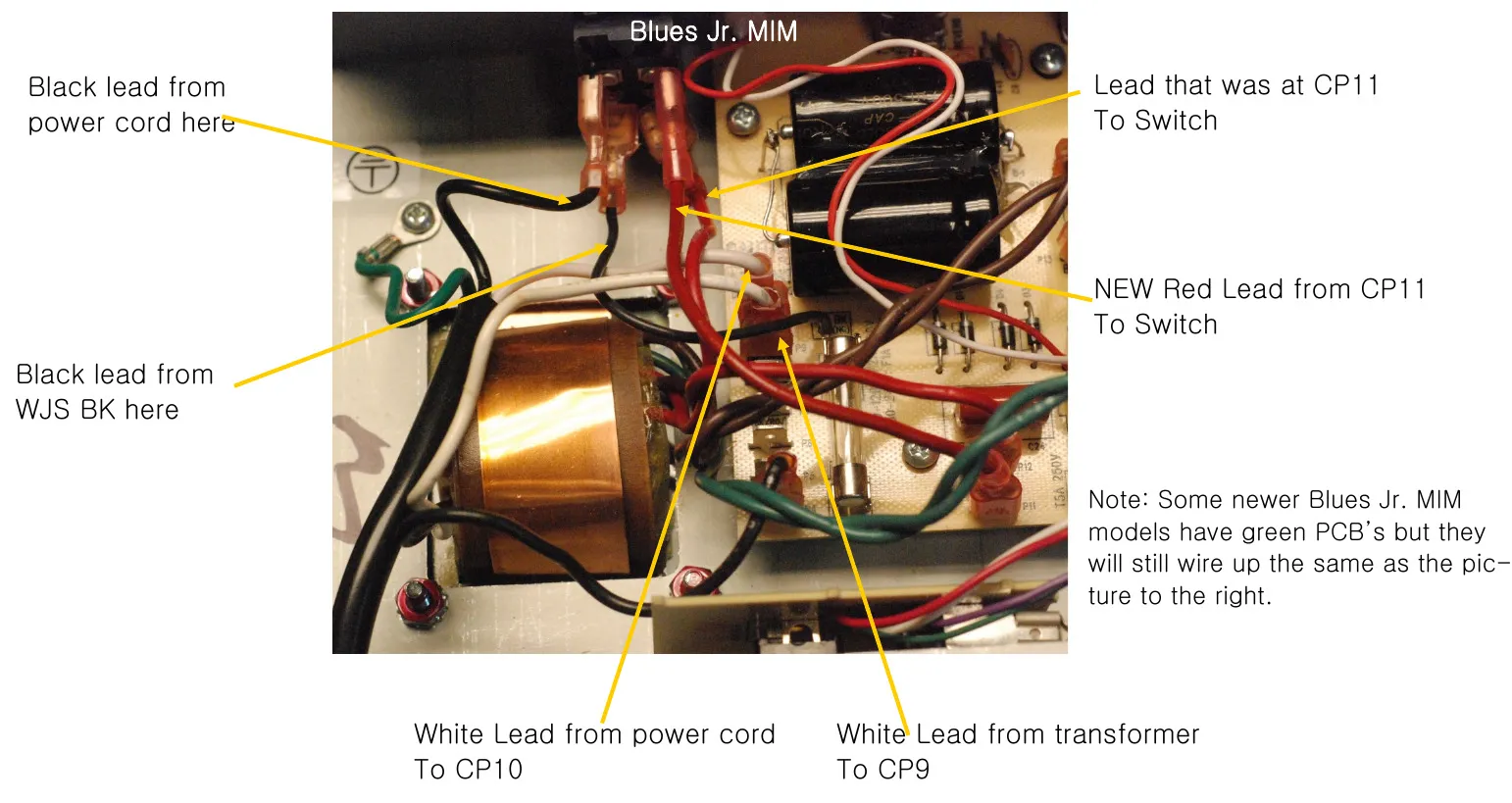
- Black lead from power cord here
- Black lead from WJS BK here
- Lead that was at CP11 To Switch
- NEW Red Lead from CP11 To Switch
- White Lead from power cord To CP10
- White Lead from transformer To CP9
- Note: Some newer Blues Jr. MIM models have green PCB’s but they will still wire up the same as the picture to the right.
10
Putting the Amp Back Together
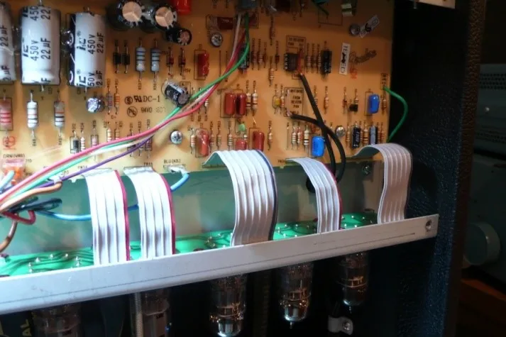
- Make sure all the ribbon cables have a smooth path with no kinks or sharp turns in the cable.
11
Step 11
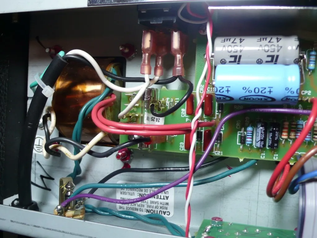
- Dress the Transformer leads!!! The poor lead dress is a large part of the noise in this amp. Instead of using a new cable tie to put the wires back like we found them we are going to use standard wiring techniques for proper tube amp design. Twist the green heater wires and position as shown. All other lead pairs should cross each other at 90 degree angles to avoid noise, hum, and oscillation.
12
Step 12
- Replace the back panel and make sure to tighten the chassis screws if you loosened them.
Finishing up
ENJOY YOUR NEW AMP