Amp Mods · Epiphone Vale Jr. Mod Kit
Epiphone Valve Jr Mod Kit Instructions
Thanks for purchasing the Epiphone Valve Jr. Supreme Modification Kit. After these simple
Optional Tools/Supplies:
- Hot Glue Gun and Hot Glue.
- 9/16” nut driver or socket wrench.
- 1/2” nut driver or socket wrench.
- Fine point Sharpie Masking Tape
- Exacto Knife
Skills required:
- Basic soldering skills .
- Basic knowledge of electronics.
- The Ability to follow instructions.
Resistor Guide
- BLACK 0 K
- BROWN 1 N
- RED 2 R
- ORANGE 3 O
- YELLOW 4 Y
- GREEN 5 G
- BLUE 6 B
- VIOLET 7 V
- GREY 8 E
- WHITE 9 W
Before starting I would like you to be a little bit familiar with the circuit and with how the changes you are about to make affect the sound and performance of your amp. There are three different versions of the Valve Jr. All of them have the same basic schematic with different part values. The newer Valve Jr’s address some of the problems the older ones had but even the latest version if the Valve Jr will benefit greatly from these mods.
Changed Components:
J1: Input Jack—Some Valve Jr’s have a metal input jack that is grounded directly to the chassis. Use the provided isolation washers to break any potential ground loop and 60Hz hum that this may cause. If your amp has a plastic and metal jack it is already isolated and does not need the washers.
R2: Grid Resistor—Stock value of 68K is too high and restricts signal, replace with the 10K resistor to keep the signal strong and prevent radio frequency interference.
R1: Pull Down Resistor– Older Valve Jr’s have a stock 68K, increase R1 to 1M for increase in overall gain and improve the signal to noise ratio.
R8 and R9 : Cathode Resistor– Stock value of 2K2 runs the pre-amp tube a little on the cool side, lowering to 1k increases the current and bias for a warmer, smoother pre-amp stage.
C1 & C2: Coupling Caps— Replaces the stock caps with the same value—High Quality Orange Drop caps for better tone.
C4 : Cathode Cap—The stock 22uf cap lets full range through the first pre-amp stage, replace with 2.2uf cap to roll off just a bit of the bass for a tighter response.
C5 : Cathode Cap—The stock 22uf cap is a little low for the power tube. Replace with 100uf cap to stabilize and stiffen the power tubes response.
R14: Cathode Resistor—The stock 220 Ohm resistor runs the power tube too hot, reducing the tubes lifespan and causing a brittle tone. Replace with 270 Ohm resistor to cool the tube, increasing its life and improving tone.
C6: Filter Cap—The first filter stage of 22uf is pretty weak. Replace with 100uf cap to reduce hum and have more reserve power for increased bass response and punch.
Brightness Mod: - a 100pf cap is placed across the volume pot, brightens up the amp at low volumes and loses its effect as you turn up the gain.
Parts
- Capacitor 100pf MLCC (Code 100)
- Capacitor .022 WIMA 10mm (Code 223) × 2
- Capacitor 2.2u 50v (Code 2.2)
- Capacitor 100u/16v (Code 100)
- Capacitor 100uf/400v (Code 100)
- Resistor 1m 1/2w (Code NKKYN)
- Resistor 10k 1/2w (Code NKKRN)
- Resistor 270ohm 2w (Code RVNG)
- Resistor 1k 1/4w (Code NKKNN) × 2
- Washer flat
- Washer shoulder
- Resistor 5W (To Safely Drain Filter Capacitors)
Tools
- Temperature Controlled Soldering Iron and Solder
- Solder Sucker and or de-soldering braid
- Multi-Meter Capable of reading 500V DC
- Phillips Screwdriver
- Pliers with insulated handle
- Wire Cutters
- Safety Goggles
- Alligator Leads
- 10 Ohm 10W power resistor or similar low ohm high wattage resistor (for draining the filter caps)
Step 1
- WARNING: Performing these modifications WILL void the warranty on your amplifier. Working on amps can be deadly if you do not take proper precautions. Follow these instructions very carefully. If you are at all unsure of your ability to perform these modifications STOP and take your amp to a professional to be modified. You can also send your amp to me for modification.
- No Warranty: This kit and the instructions included do not include any warranty of any kind. The modifications to your amplifier are at your own risk and you agree to completely hold harmless the seller of this kit against any and all claims. Tube amplifiers contain parts that operate at very high temperatures and deadly voltages. If you are not sure of your abilities to perform these modifications then do not perform them.
Prep the Amp
- Instructions: Follow these instructions to the letter. And read them through a couple times before starting.
- It’s a good idea to have all the parts and tools you will need laid out before starting in a well lit area.
- Unplug the Amp and put on your safety goggles.
Step 3
- DON’T KILL YOURSELF: DRAIN THE FILTER CAPS: Measure the voltage on both sides of R12 relative to Ground. If this measures more than 10 VDC you need to drain the filter caps. Using insulated pliers and a low ohm high watt power resistor placed between R12 and ground for 30 seconds on both sides of R12 and measure again, keep repeating this process until the voltage reads less than 10 VDC.
Step 4
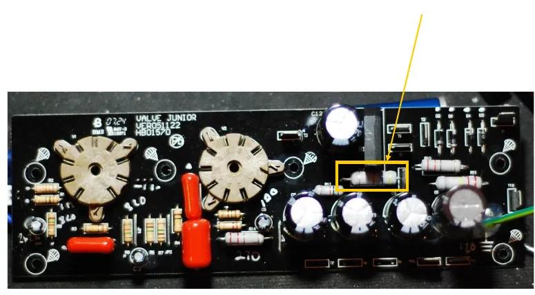
- CAUTION: Capacitors can recharge even when the amp is not plugged in!!!
- After the filter caps are drained take an alligator lead and clip one end to R12 and the other end to the Ground and leave it there until you are done with your work. This will prevent the filter caps from re-charging.
Step 5
- CAUTION: The circuit board is fragile and the solder pads can easily become separated from the circuit board if extreme care is not used. Carefully examine each solder pad after removing the component to make sure the solder pad is intact. If the solder pad is damaged you will need to carefully scrape away the solder mask of the trace next to the hole, bend the lead to the trace and solder directly to the trace. Remember to always check continuity with your multimeter to insure that you have a good connection between components.
- Never force components out of their holes, remove the solder with a sucker and de-soldering braid and clip component leads from the component side of the board.
Step 6
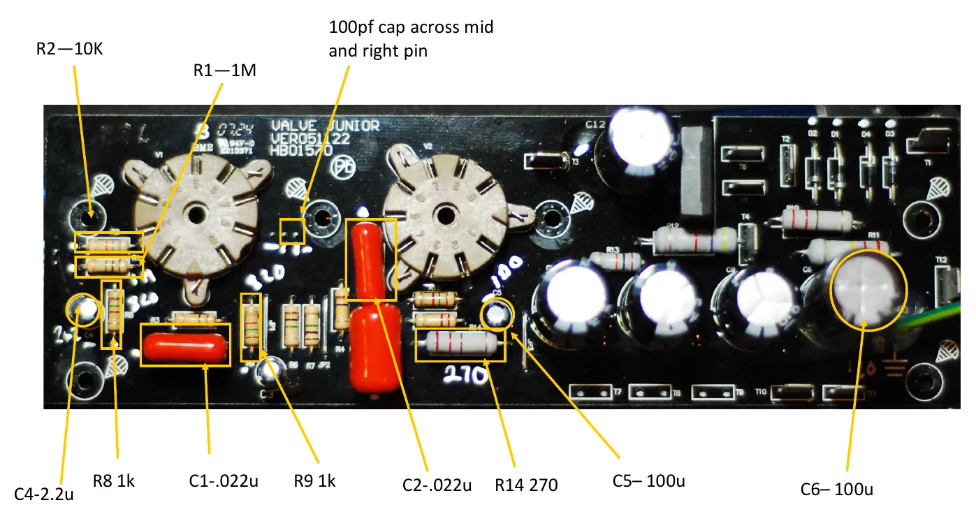
- MIND YOUR POLARITY ON DIODES AND ELETROLYTIC CAPS: Pictured below are both the newer Black Board and the older Greed Board PCB—Notice that the Layout is almost identical.
- R2—10K
- R1—1M
- 100pf cap across mid and right pin
- C4-2.2u
- R8 1k
- C1-.022u
- R9 1k
- C2-.022u
- R14 270
- C5– 100u
- C6– 100u
Step 7
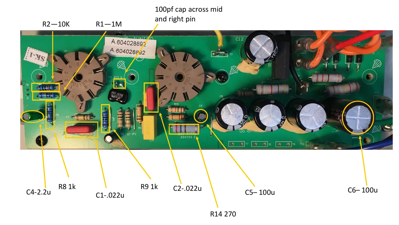
- R2—10K
- R1—1M
- 100pf cap across mid and right pin
- C4-2.2u
- R8 1k
- C1-.022u
- R9 1k
- C2-.022u
- R14 270
- C5– 100u
- C6– 100u
Tips
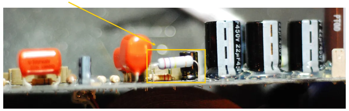
- When installing R8 mount it so it sits off the board about 1/4 inch, this will help to dissipate heat.
Step 9
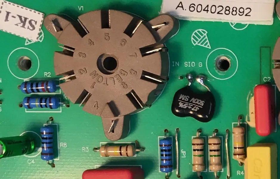
- Close up after the new parts are installed, note how the 47pf cap is soldered on.
Step 10
- Caution: Never force the old components out of the board. Use a solder wick and solder sucker to remove the solder, clip the leads from the component side of the board and carefully remove the leads from the holes. Some components may be hot-glued to the board, carefully remove the hot glue with an exacto knife. The PCB is fragile and if excessive heat is used or if components are forced out of the board the solder pads can lift or become damaged.
Step 11
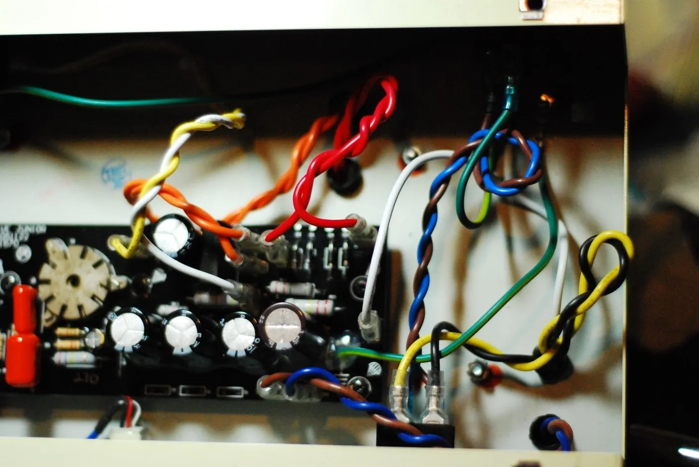
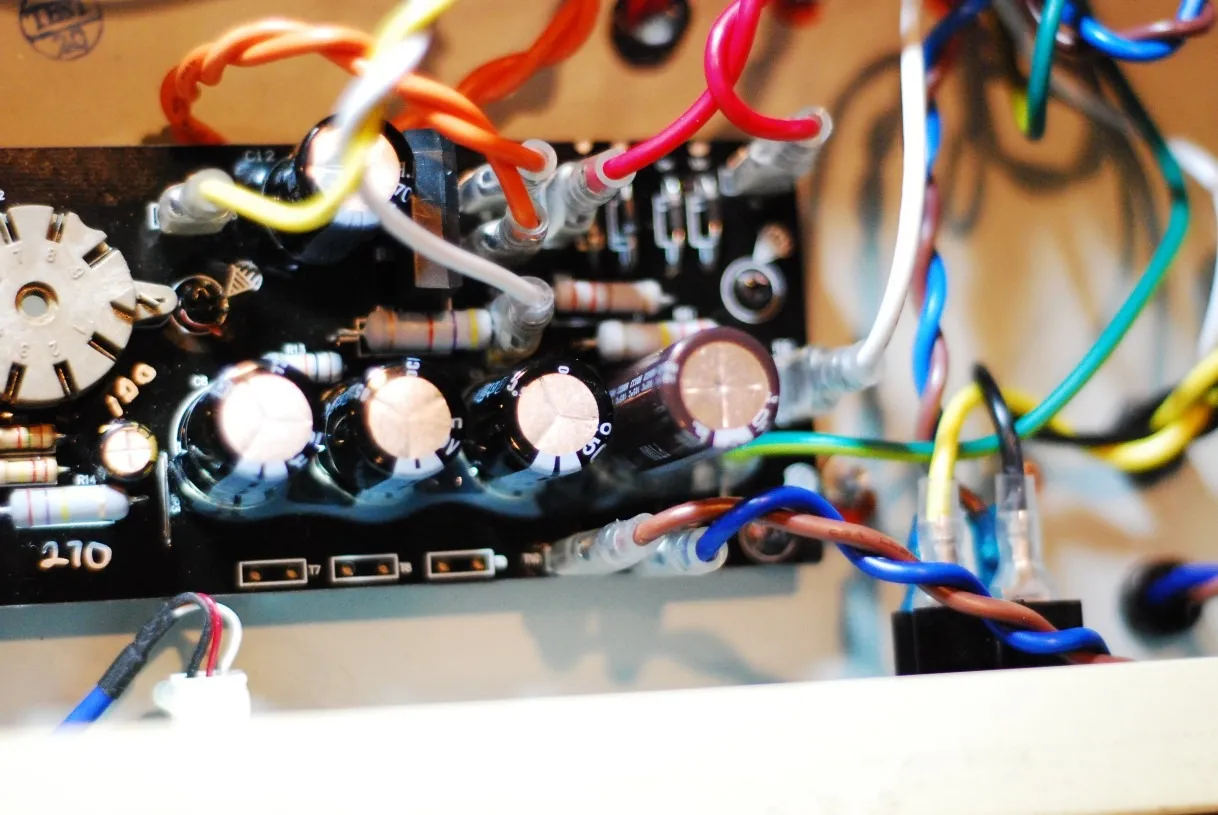
- Proper Lead Dress: Note how the pairs of wires are carefully twisted and pairs cross each other at right angles if possible. Proper lead dress will reduce noise, hum and help prevent oscillation.
Step 12
- Double check all your work, make sure your solder joints are clean and all your leads clipped and every wire is connected back where you found it. Put the amp back together and you are ready to ROCK!