Pedal Mods · Boss OS-2 Mod Kit
Boss OS-2 Overdrive Distortion Mod Kit Instructions
Thank you for purchasing the OS-2 Supreme Mod Kit. After these mods you will not believe it’s even the same Pedal. Included are all the components necessary for total tone transformation, it replaces key components in the signal path to turn your OS-2 into a serious tone machine.
RESISTOR CODES
- BLACK 0K
- BROWN 1N
- RED 2R
- ORANGE 3O
- YELLOW 4Y
- GREEN 5G
- BLUE 6B
- VIOLET 7V
- GREY 8E
- WHITE 9W
Parts
- CAP 100P (CODE 101)
- CAP 0.01 (CODE 103)
- CAP 1U (CODE 105) × 2
- CAP 0.022 (CODE 223)
- CAP 0.22 (CODE 224)
- CAP 0.047 (CODE 473) × 2
- DIODE 1N34A (CODE GLASS) × 2
- DIODE 1N4007 (CODE BLACK) × 3
- RESISTOR 1K (CODE NKKNN)
- RESISTOR 10K (CODE NKKRN) × 3
- RESISTOR 27K (CODE RVKRN)
- IC NE5532P
- SOCKET 8PIN
- LED 3MM (CODE YELLOW)
1
Step 1
- CAUTION: Read all these instructions before beginning, if you pedal is currently under warranty it will not be after these mods. This kit and the instructions do not include any warranty of any kind and you agree to hold harmless the seller of this kit against any and all claims.
2
Step 2
- Start by sorting out all the parts in the kit, the chart below will help.
3
Step 3
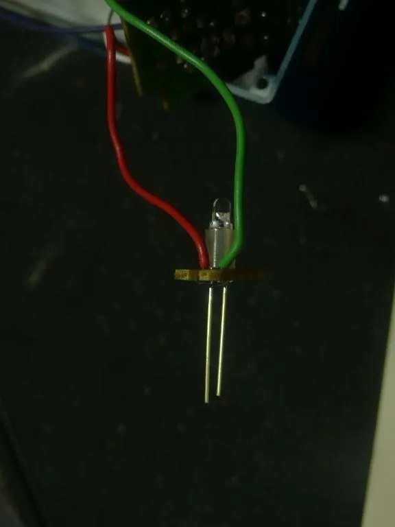
- There is also a new LED to replace the red one, it will not change the tone of the pedal, just change the color of the light. The longer lead goes to the red wire.
4
Step 4
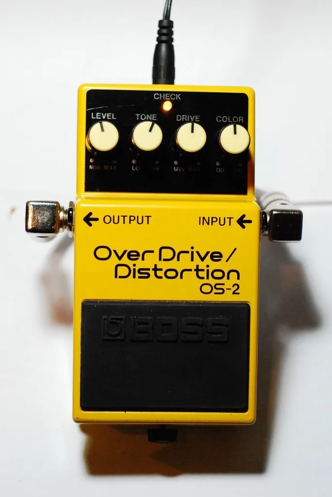
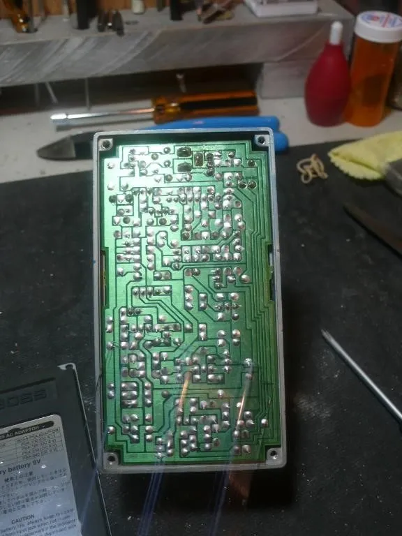
- Next Open up the back and take a look inside. There is the main circuit board and a tiny board that only houses the LED. There is no need to remove the jacks or pots for this Kit.
5
Step 5
- After the board is exposed it’s time to start removing components and replacing them with the new ones. Make sure the battery is removed and no cables or AC-adaptors are plugged in. On Page 3 is a detail of the OS-2 board before all the components are removed and which components will be replaced. Note that there are two components behind the ribbon cable.
6
Step 6
- If you are quite confident of your abilities you can remove all the components in one step then go through and replace them all. However if this is your first time modding a pedal you may want to replace the parts one at a time, then test the pedal. You don't need to completely put the pedal back together every time you test it as it will work perfectly fine with all the guts exposed. You may also like to hear the progress you are making as you go. Some parts will have a more drastic effect than others. Don’t ever touch the soldering iron to the pedal while the pedal is plugged in.
7
Step 7
- The PCB is pretty resilient , however, you need to be careful not to force the old components out of the holes as this can damage the traces and solder pads. Instead use a solder sucker and de-soldering braid to remove all the solder so that the old components are removed with ease. I find that it is a good idea to clip the lead on the top side of the board before de-soldering.
8
Step 8
- The diodes and the IC must be inserted correctly in order to work. The diodes have a band closest to the positive side and the PCB has an arrow pointing toward the positive side. For the IC note the direction of the dent or dot on the chip and the PCB. Install the socket on the board in the correct way, then you can try out any dual op-amp and see the changes in the sound. Note on page 4 the completed photo shows the empty socket, you will need to insert a chip for the pedal to work.
9
Step 9
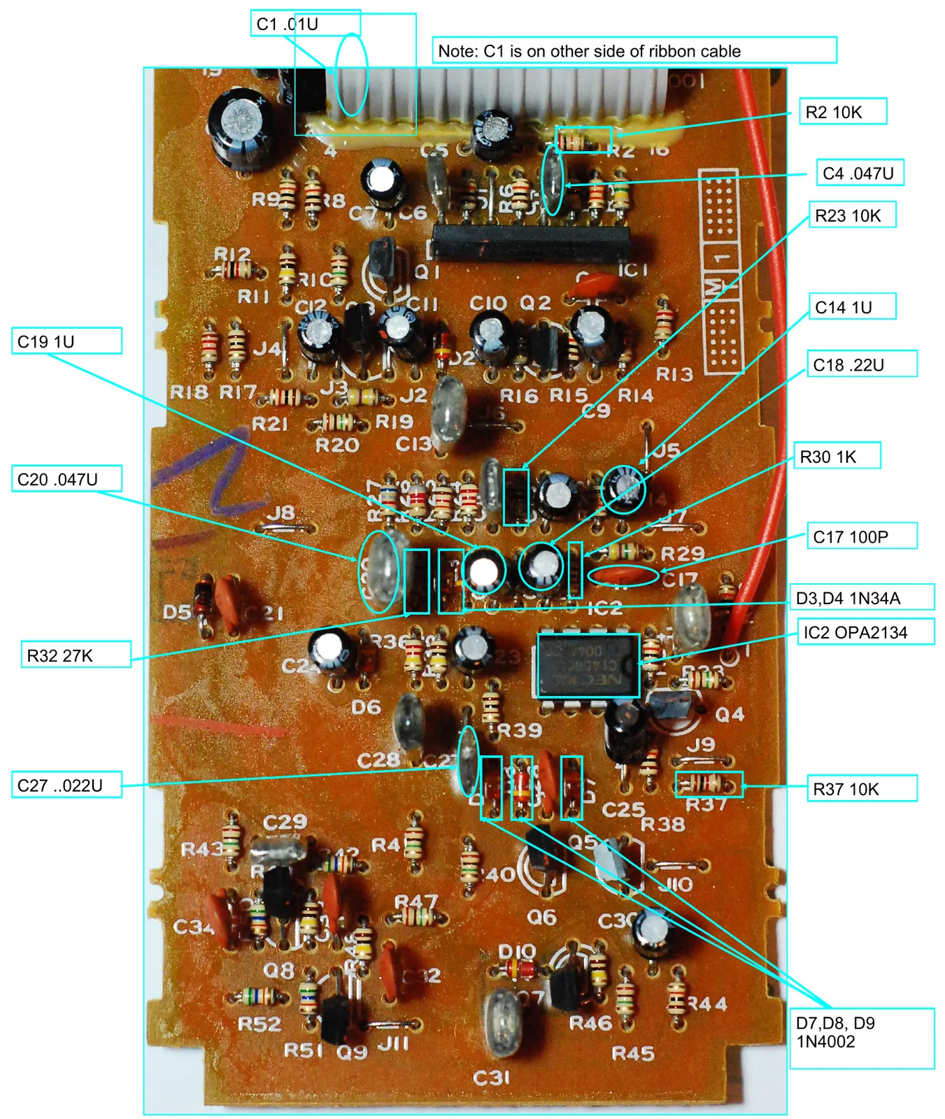
- C1 .01U
- Note: C1 is on other side of ribbon cable
- R2 10K
- C4 .047U
- R23 10K
- C14 1U
- C19 1U
- C18 .22U
- R30 1K
- C20 .047U
- C17 100P
- D3,D4 1N34A
- IC2 OPA2134
- R32 27K
- C27 ..022U
- R37 10K
- D7,D8, D9 1N4002
10
Step 10
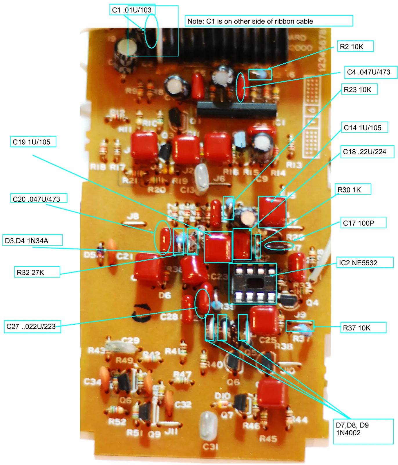
- C1 .01U/103
- Note: C1 is on other side of ribbon cable
- R2 10K
- C4 .047U/473
- R23 10K
- C14 1U/105
- C19 1U/105
- C18 .22U/224
- R30 1K
- C20 .047U/473
- C17 100P
- D3,D4 1N34A
- IC2 NE5532
- R32 27K
- C27 ..022U/223
- R37 10K
- D7,D8, D9 1N4002