Vintage Recap Kits · Princeton Recap Kit
Fender Princeton Recap Kit
Optional Tools/Supplies:
- Silicone glue.
- 9/16” nut driver or socket wrench.
- 1/2” nut driver or socket wrench.
- Fine point Sharpie or similar permanent marker.
- Masking Tape
Skills required:
- Basic soldering skills .
- Basic knowledge of electronics.
- The Ability to follow instructions.
NOTE: Capacitor voltage values may vary some from that specified.
Parts
- 20uf-20uf-20uf-20uf/475v Can-cap
- 22uf/50v AXIAL × 7
- 5W Resistor AXIAL
Tools
- Temperature Controlled Soldering Iron and Solder
- Solder Sucker and or de-soldering braid
- Multi-Meter Capable of reading 500V DC
- Phillips Screwdriver
- Pliers with insulated handle
- Wire Cutters
- Safety Goggles
- Alligator Leads
1
Step 1
- No Warranty: This kit and the instructions included do not include any warranty of any kind. The modifications to your amplifier are at your own risk and you agree to completely hold harmless the seller of this kit against any and all claims. Tube amplifiers contain parts that operate at very high temperatures and deadly voltages. If you are not sure of your abilities to perform these modifications then do not perform them.
- Caution! Drain the filter caps!
- The filter caps on your amp may be drained already but you must follow these steps to insure that any deadly voltage is removed from the amp before you begin work.
2
Disassemble the amp
- Remove the back plate, unplug the speaker, reverb, and footswitch cables from the back of the amp chassis.
3
Step 3
- If you don’t have an amp repair stand, remove the tubes, noting each tube’s location.
4
Step 4
- Unscrew the P shaped bracket holding the power cord inside the cab. I usually take the bracket off the cord and screw it back into the same hole so I don’t lose it while I work on the amp.
5
Step 5
- Unscrew and remove the chassis straps from the top of the cab.
6
Step 6
- Slide the chassis back and out.
7
Step 7
- Danger! This must be done to avoid injury!
- Test the voltage across the filter caps. Set your multi meter to DC and measure the voltage at the location circled in red on the diagram for your amp, using the chassis as ground. If the voltage reads higher than 10 volts, drain the caps further by clipping one end of an alligator clip jumper to the chassis (ground), the other end to one lead of the included 5W Resistor and then touching the other lead of that resistor it to the circled spot to safely drain the voltage from the circuit. Then, measure again to make sure the voltage has drained and the amp is safe to work on.
8
Step 8
- Follow the diagram for your amp found on the following pages, replacing the marked capacitors with the listed capacitors. Make sure to keep track of the symbols on each lug of the can cap when replacing it.
9
Step 9
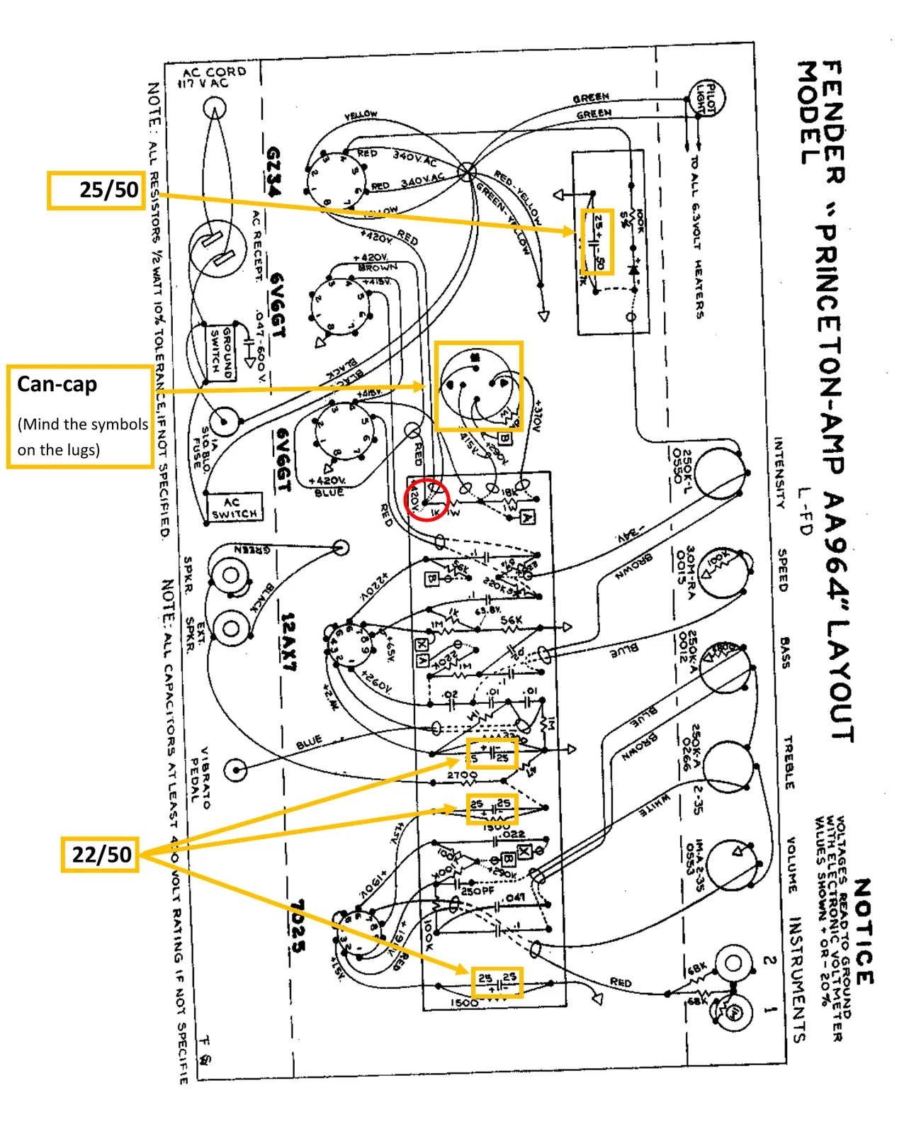
- 25/50
- Can-cap
- (Mind the symbols on the lugs)
- 22/50
10
Step 10
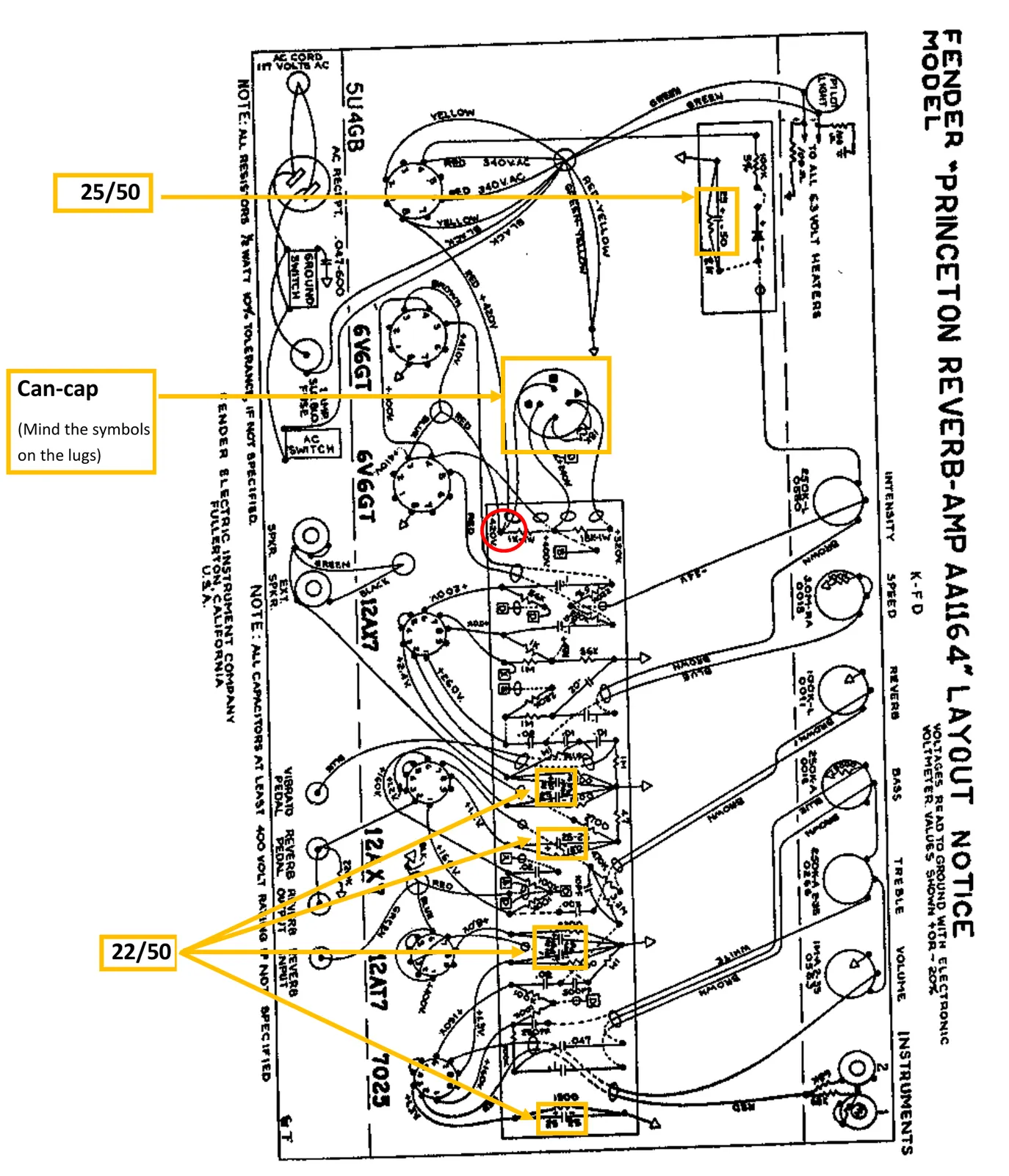
- 25/50
- Can-cap
- (Mind the symbols on the lugs)
- 22/50