Pedal Mods · Boss OD-1 Mod Kit
Boss OD-1 Overdrive Mod Kit
Thank you for purchasing the OD-1 Supreme Mod Kit. After these mods you will not believe it’s even the same Pedal. Included are all the components necessary for total tone transformation, it replaces most every component in the signal path and turns the OD-1 into a serious tone machine. If you have a basic understanding of electronics and know how to solder you can get this done in about 1/2 hour.
Parts
- 0.1 Film Cap 104 × 3
- 1u Film Cap 105 × 2
- 0.047 Film Cap 473
- 47p Cer Cap 47
- 47uf EL Cap 47uf
- 100uf EL Cap 100uf
- 3k3 Resistor OOKNN
- 680k Resistor BEKON
- 1k Resistor BKKNN
- 1 socket 8PIN
- NE5532 Opamp NE5532
- 1n34a Ger Diode GLASS × 2
- 1n4007 Rec Diode BLACK × 2
- Yellow LED LED
1
Step 1
- CAUTION: Read all these instructions before beginning, if you pedal is currently under warranty it will not be after these mods. This kit and the instructions do not include any warranty of any kind and you agree to hold harmless the seller of this kit against any and all claims.
2
Step 2
- Start by sorting out all the parts in the kit, the chart below will help.
- RESISTOR CODES
- BLACK 0K
- BROWN 1N
- RED 2R
- ORANGE 3O
- YELLOW 4Y
- GREEN 5G
- BLUE 6B
- VIOLET 7V
- GREY 8E
- WHITE 9W
3
Step 3
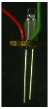
- There is also a new LED to replace the red one, it will not change the tone of the pedal, just change the color of the light. The longer lead goes to the red wire.
4
Step 4
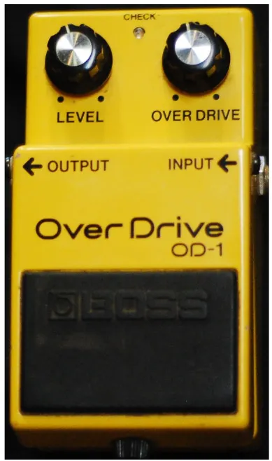
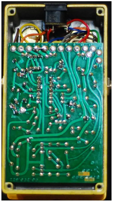
- Next Open up the back and take a look inside. There are two circuit boards. The main board in the picture, , and a tiny board that only houses the LED. We will need to get to both boards but there is no need to remove the knobs or the input or output jacks.
5
Step 5
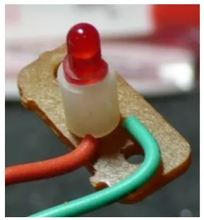
- There is a small circuit board that holds the Red LED. Your kit has a water clear bright LED to replace this with. This change is not necessary but it does make the pedal look much cooler. LED’s are polarized and only work one direction The longer lead of the LED is the positive side orange wire.
6
Step 6
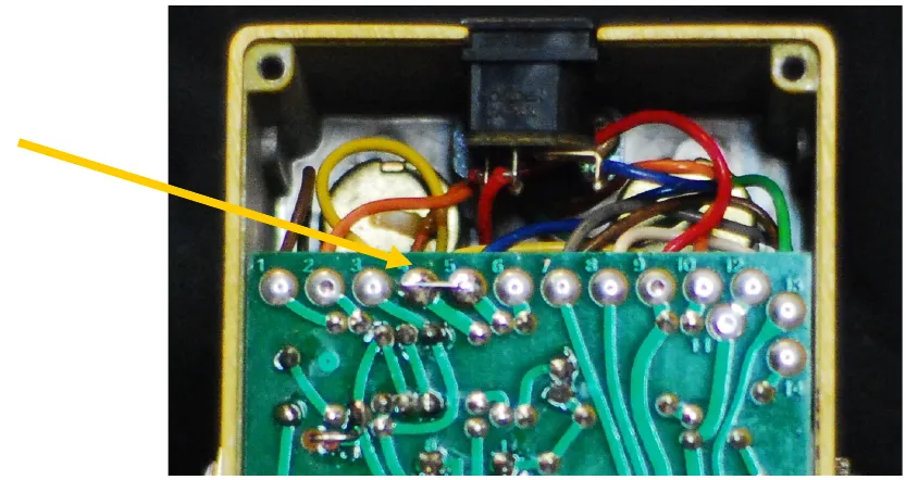
- If you want to use the pedal with a normal PSA Boss Style adaptor place a jumper between wires 4 and 5 as indicated here
7
Step 7
- Sort out the parts for the mod. I recommend putting the socket in for the Op-amp. If you are careful with removing the original you can still use it and you will be able to swap out different op-amps in a heartbeat. None of the resistors or caps are polarized so they can be inserted either direction. The op-amp must be inserted as shown in the photo on the next page. There is usually a dot next to pin one of any op-amp and there is also a notch indicating direction. For the Diodes the arrow on the board points to the side that the band is closest to. The mods require two diodes in series where there was only one before. See the photo below for how to wire this up. The filter caps are inserted with the negative side (short lead) closest to the dot by the caps C17 and C9
8
Step 8
- Use care when removing the old components, use a solder sucker and de-soldering braid and never force a component out of the board. This could damage the solder pads on the board.
9
Step 9
- Use the diagram on the next page to help you identify the location of the components.
10
Step 10
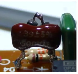
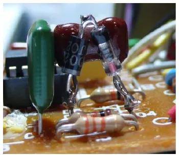
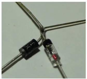
- See the detailed photo’s below on how to wire up D5 on the circuit board, there is a 1n34 and 4001 in series with the mica cap in parallel to both.
11
Step 11
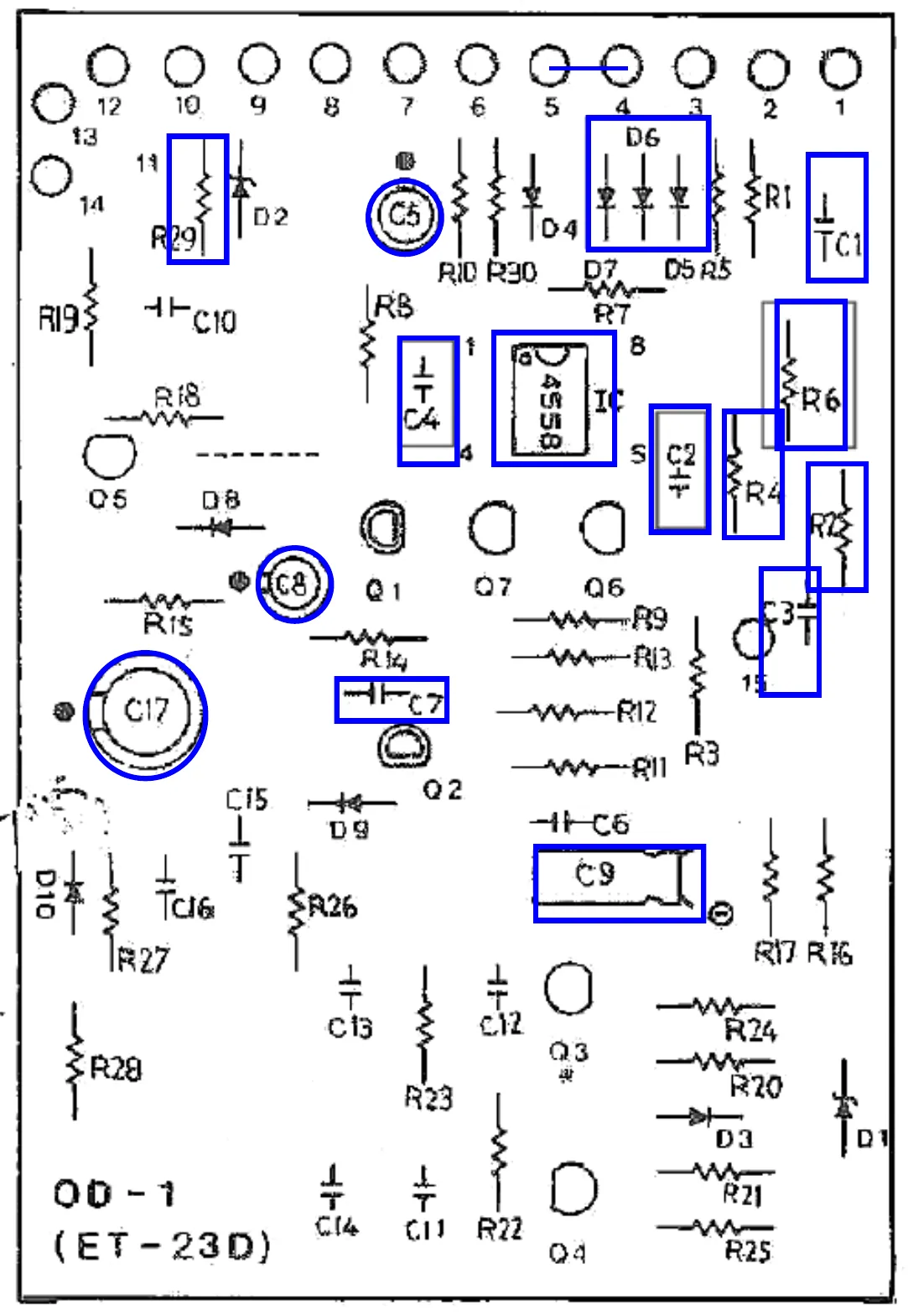
- Your circuit board may or may not have the component numbers listed on the board, use the diagram below to see what components are being changed/removed.
12
Step 12
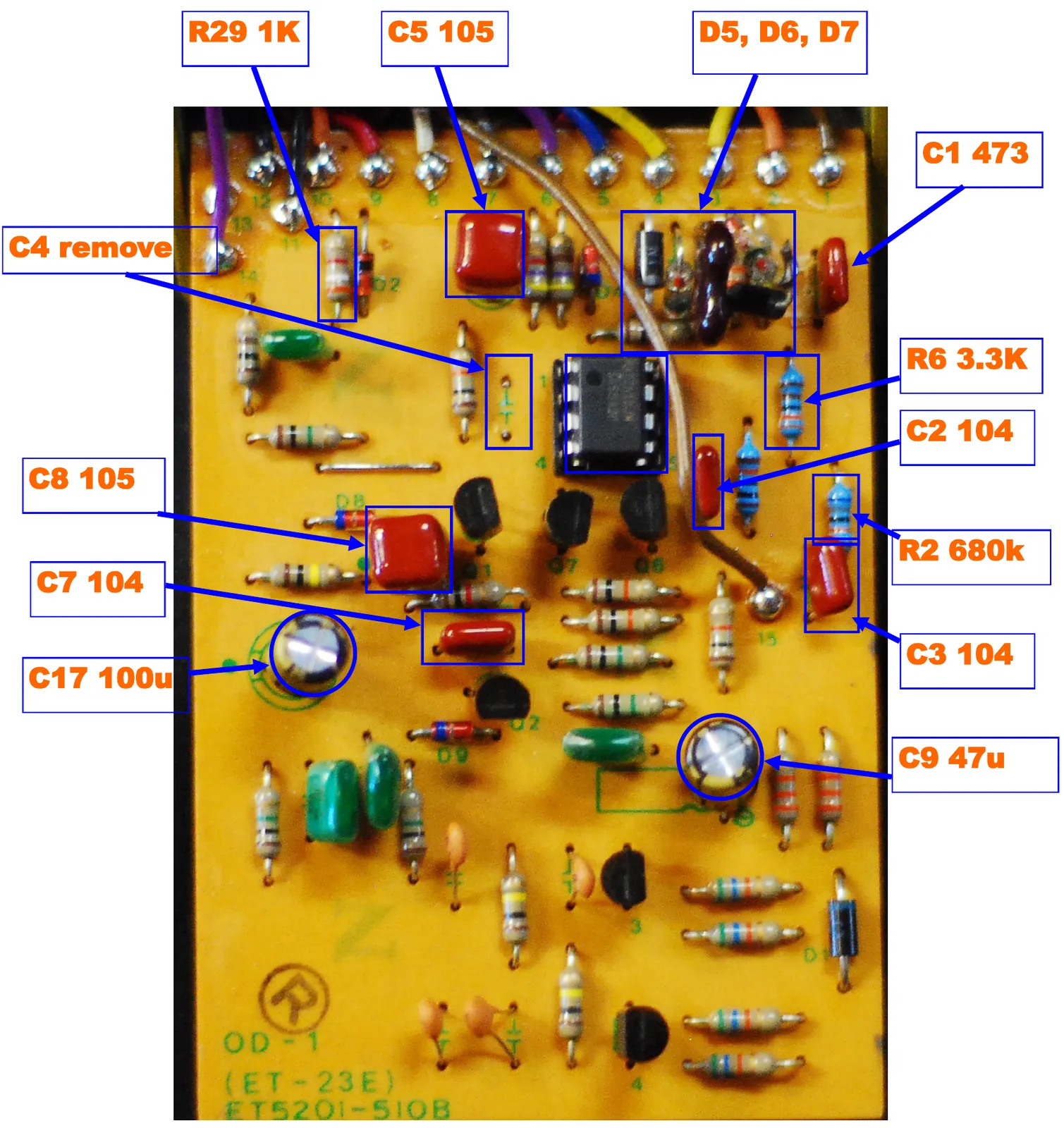
- R29 1K
- C5 105
- D5, D6, D7
- C1 473
- C4 remove
- R6 3.3K
- C2 104
- C8 105
- R2 680k
- C7 104
- C3 104
- C17 100u
- C9 47u