Recap Kits · Custom Vibrolux Reissue Recap Kit
Fender Custom Vibrolux and Vibroverb Re-Cap Kit
Optional Tools/Supplies:
- Silicon.
- 9/16” nut driver or socket wrench.
- 1/2” nut driver or socket wrench.
- Fine point Sharpie or similar permanent marker.
- Masking Tape
Skills required:
- Basic soldering skills .
- Basic knowledge of electronics.
- The Ability to follow instructions.
Tips: Be careful when removing parts from the circuit board, NEVER FORCE A PART OUT. Use a solder sucker and solder braid to remove solder. I like to clip the leads of the old parts when possible before removing the lead from the PCB. The PCB is fragile and too much heat can cause the solder pad to lift off the board.
Parts
- 22/35 AXIAL × 6
- 22/500 AXIAL × 5
- 47/500 AXIAL
- 22/63 RADIAL
- 100/100 RADIAL
- 330 OHM RESISTOR
Tools
- Temperature Controlled Soldering Iron and Solder
- Solder Sucker and or de-soldering braid
- Multi-Meter Capable of reading 500V DC
- Phillips Screwdriver
- Pliers with insulated handle
- Wire Cutters
- Safety Goggles
- Alligator Leads
1
Step 1
- WARNING: Performing these modifications WILL void the warranty on your amplifier. Working on amps can be deadly if you do not take proper precautions. Follow these instructions very carefully. If you are at all unsure of your ability to perform these modifications STOP and take your amp to a professional to be modified. You can also send your amp to me for modification.
- No Warranty: This kit and the instructions included do not include any warranty of any kind. The modifications to your amplifier are at your own risk and you agree to completely hold harmless the seller of this kit against any and all claims. Tube amplifiers contain parts that operate at very high temperatures and deadly voltages. If you are not sure of your abilities to perform these modifications then do not perform them.
- CAUTION: TUBE AMPLIFIERS CAN CONTAIN DEADLY VOLTAGES EVEN WHEN THEY ARE NOT PLUGGED IN—BE SURE TO DRAIN THE FILTER CAPS BEFORE WORKING ON THE AMP—NOT DRAINING THE FILTER CAPS COULD RESULT IN SERIOUS INJURY OR DEATH.
2
Prep the Amp
- Instructions: Follow these instructions to the letter.
- It’s a good idea to have all the parts and tools you will need laid out before starting in a well lit area.
- Unplug the Amp and put on your safety goggles.
3
Step 3
- Remove the tubes, unplug the speaker, unplug the reverb from the reverb can (be sure to note which side is red and which side is black, remove the clips holding the reverb wire and power cable to the cabinet.
4
Step 4
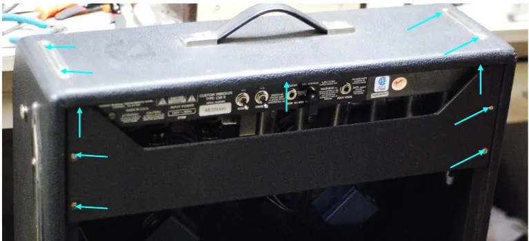
- Remove the screws holding on the back panel and remove the panel. Then remove the chassis screws.
5
Step 5
- The chassis should slide out easily exposing the circuit board I find it easiest to work on the amp with the chassis completely removed from the cabinet.
6
Step 6
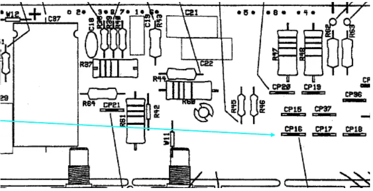
- WARNING: SKIPPING THIS NEXT STEP COULD RESULT IN DEATH
- Drain the Filter Caps: Using your multimeter set to DC measure the voltage at CP16 to ground. If the voltage is more than 15 VDC you need to drain the caps. It’s good practice to keep your left hand in your pocket and work only using your right hand. Then if you do touch something that is high voltage while grounded the current will hopefully go though your right hand to ground and miss your heart. Clip an alligator lead to C16 and to the 330 ohm power resistor, clip another alligator lead from the other side of the resistor to ground. Measure the voltage every minute until the reading is less than 15 VDV. Capacitors can recharge even when the amp is not plugged in!!! Clip an alligator lead from C16 to ground and leave it there. This will prevent the filter caps from re-charging.
7
Step 7
- Remove all the transformer leads and leads from the bone yard (where the filter caps are under the chassis. Be carful to note where each lead goes. I like to put a bit of masking tape on each lead and write the number it goes to in sharpie.
8
Step 8
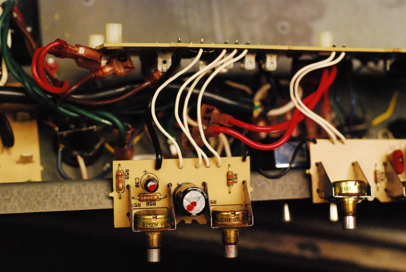
- Remove the small PCB holding the Speed and Intensity control by removing the knobs and washers from the chassis. This is where the 22/63 and 100/100 radial caps will go. I like to replace these caps then put the small PCB back before continuing. Be sure to mind the polarity of the caps.
9
Step 9
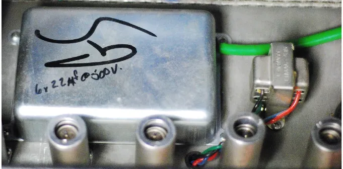
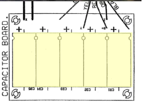
- I like to replace the caps in the bone yard next, turn the chassis over and expose the bone yard by removing the four screws holding it to the chassis, Remove the PCB and replace all the 22uf/500v caps. (Be sure to mind the polarity). I like to clip the leads and remove the caps from the board before desoldering the leads from the PCB. It’s also a good idea to use a bit of silicone to glue the new caps to the board
- Put the bone yard back together and turn the chassis back over to work on the main PCB.
10
Step 10

- Remove all the screws holding the main PCB. I like to clip the leads and remove the caps from the board before removing the leads from the PCB. Replace all the other caps as indicated on the diagram below. Be sure to mind the polarity of the caps.
- C1 22/35 AX
- C6 22/35 AX
- C12 22/35 AX
- C14 22/35 AX
- C15 22/25 AX
- C25 22/25 AX
- C37 47/500 AX
11
Step 11
- CAUTION: The circuit board is very fragile and the solder pads can easily become separated from the circuit board if extreme care is not used. Carefully examine each solder pad after removing the component to make sure the solder pad is intact. If the solder pad is damaged you will need to carefully scrape away the solder mask of the trace next to the hole, bend the lead to the trace and solder directly to the trace. Remember to always check continuity with your multi-meter to insure that you have a good connection between components.
12
Step 12
- Make sure you mind the polarity of the caps, they must be inserted the right way or your amp will have problems which could be serious.
- The circuit board will have a “+” sign closest to the hole where the positive lead of the cap goes. The axial caps have an indented ring on the positive side and a “-” sign in an arrow pointing to the negative side. For radial caps the longer lead is the positive side and there is a “-” sign in a band closest to the negative terminal.
13
Putting the Amp Back Together
- Use Silicon to secure the caps to the PCB. Make sure that you have clipped all the excess leads from the solder side of the board and that all your new solder joints are secure before continuing.
14
Step 14
- Carefully put the PCB back into place making sure that none of the leads to the other boards or tube sockets have been disconnected.
15
Step 15
- Replace all of the PCB mounting screws.
16
Step 16
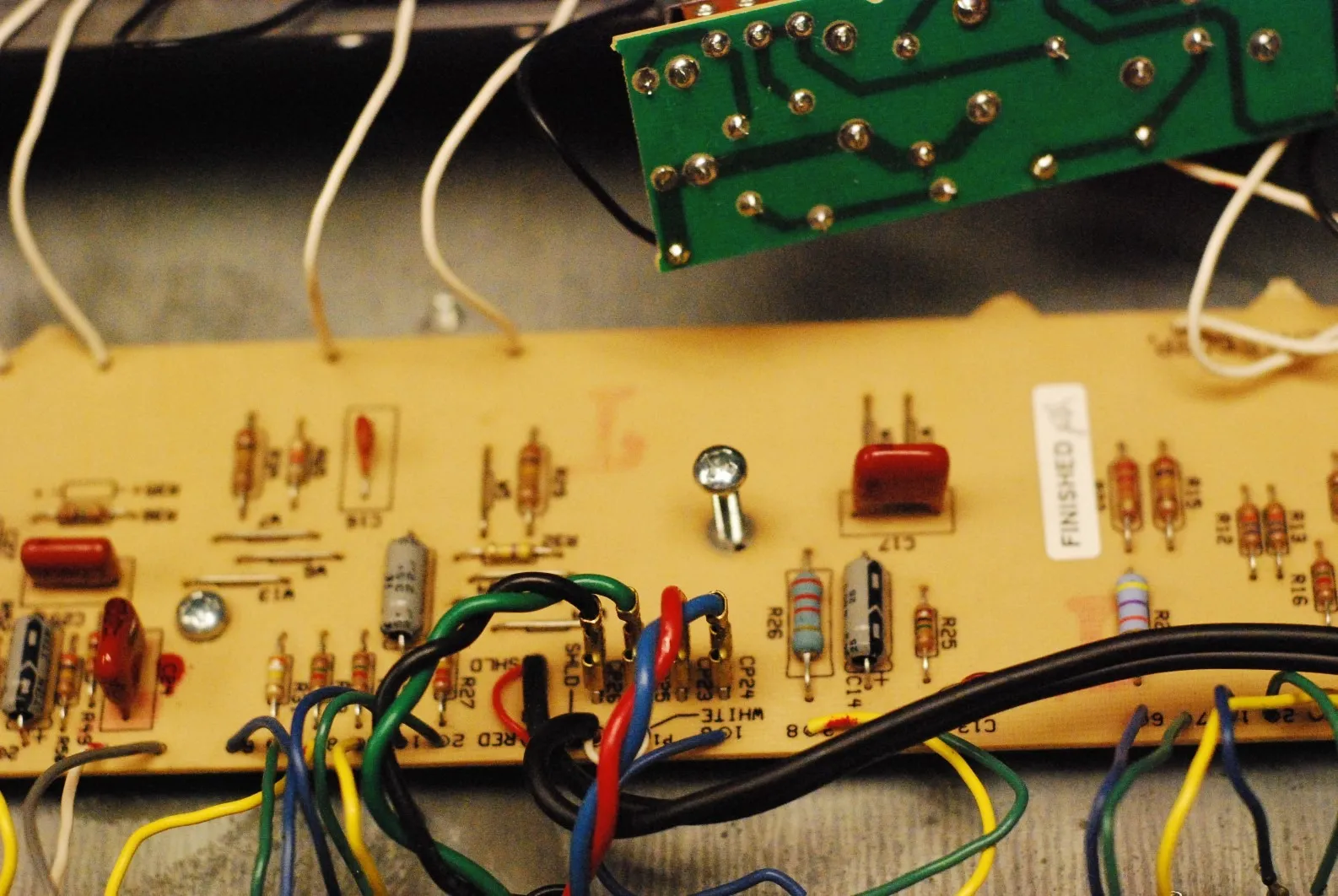
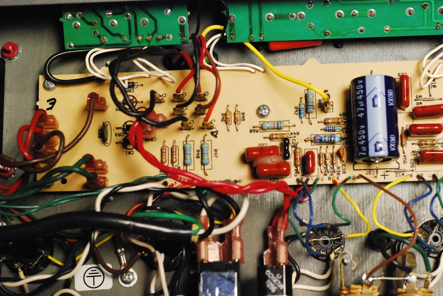
- Dress the Transformer leads!!! Poor lead dress is a large part of the noise in an amp. Instead of using a new cable tie to put the wires back like we found them we are going to use standard wiring techniques for proper tube amp design. Twist the green heater wires and position as shown. All other lead pairs should be twisted and cross each other at 90 degree angles to avoid noise, hum, and oscillation.
17
Step 17
- DOUBLE CHECK ALL YOUR WORK.
18
Step 18
- Re-install the chassis the same way you took it apart, install the three small screws holding the chassis to the top of the amp (I like to turn the amp upside down when I do this), plug in the reverb and clips holding the power cord and reverb cable. Plug in the speaker cable. Install the back panel, then the 4 main chassis screws on the top of the amp. Replace the tubes and you should be ready to rock.
Finishing up
Tip: Try swapping V3 and V6. This will put a 12AT7 in the phase inverter and a 12AX7 in the reverb driver, you should find that the reverb sound a bit better and the amp will sound more balanced with the AT7 in the phase inverter.